Approximation of Antenna Segment Lengths and Heights for Determining Theoretical Capacitance
This is to examine the case of an insulated AWG 14 solid copper wire antenna strung between and through two trees with the goal being to estimate the total antenna capacitance through the summation of individual segment capacitances.Calculation of theoretical antenna capacitance using the basic formula:

has yielded a result on the order of one third the actual measured capacitance (measured with a capacitance meter from antenna to ground). Our hypothesis is that the proximity of sections of the antenna to either tree branches and/or the side of the house where the lead-in occurs may be contributing higher than expected capacitance to the entire antenna system.
The first step is to observe the antenna geometry and make some arbitrary classifications, along with estimations of the lengths and heights of antenna sections that fall into each of these classifications.
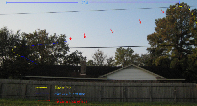
Fig. 1 - View of antenna observed looking south, from side of house
In Fig. 1, the antenna is strung from the pine tree on the right to the oak tree on the left. The free-air distance is about 25 meters. The wire makes a smooth curve through the oak tree around some branches (approximate distance - about 2 meters). There are approximately 2 meters from the oak tree to the point where the wire is looped around a hook at the top of the east side the roof.
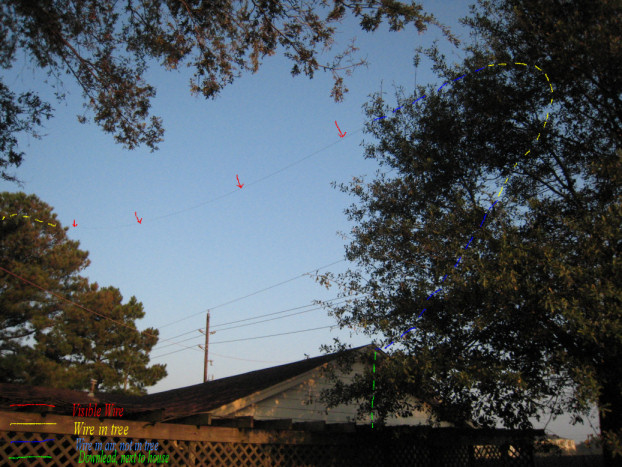
Fig. 2 - View of antenna as it loops through oak tree
Fig. 2 gives a different perspective showing how little wire is actually in contact with the oak tree. It enters the oak tree at a height of approximately 7 meters and exits at about 5 meters. There are then about 2 1/2 meters of wire in the air to the house (1 meter of vertical drop and 2 meters of horizontal run.
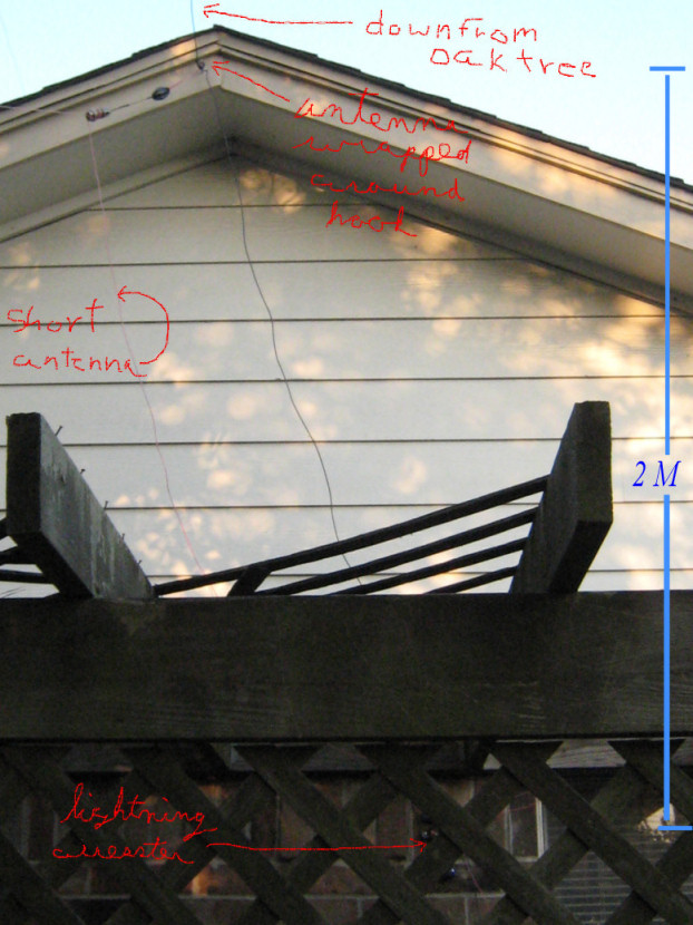
Fig. 3 - East facing of house showing antenna down lead
We can see by Fig. 3 that there are close to 2 meters of down-lead going to the lightning arrestor. Except for the contacts at top and bottom, this wire is about 0.5 meters from the side of the house.
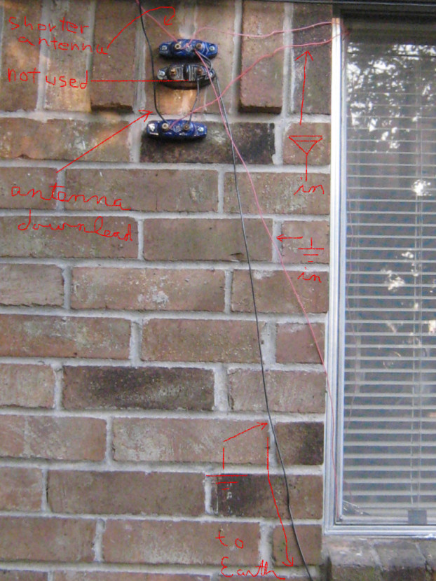
Fig. 4 - East side of house - antenna and ground lead in to house
From the lightning arrestor to the aluminum window frame is approximately 40 cm. The wire enters the house between the closed window and its frame. There is approximately one meter of wire in the house.
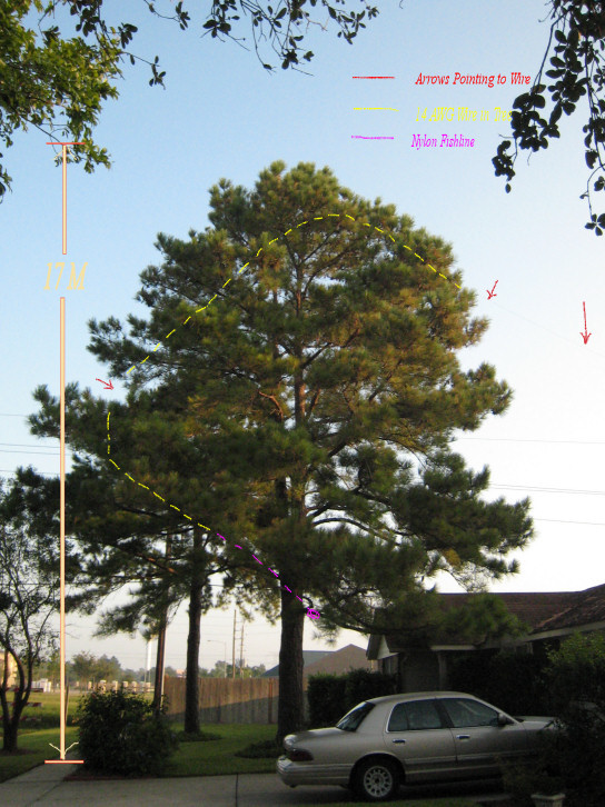
Fig. 5 - In the front yard, looking north - configuration of antenna in pine tree
Fig. 5 here suggests that the wire enters the tree somewhat lower that it actually does. (See Fig. 1 for a better view of the actual entry point.) The wire enters the tree at approximately 16 meters height. It has an approximate 3.5 meter horizontal run. The wire then angles downward at approximately 45 degrees for another 7 meters. It ends that slope at a height of approximately 11 meters. Then there is an approximate 1 meter vertical open air length descending from 11 to 10 meters. Next, there is an approximate 1 meter vertical drop through the tree as the wire descends from 10 to 9 meters. The last section of wire then turns back towards the trunk for 4 more meters at a negative 45 degree angle, descending from 9 to 6 meters in height. At that point, the wire is tied to a nylon fish line, which is itself tied to a tree branch.
To summarize what we have observed we put the data into this table. The table starts from the point in the pine tree where the nylon fishing line is tied to the end of the antenna and records segment information up to the entry point to the house on the east side. (All heights and lengths are in meters.)
| Antenna Segment Parameters | ||||||
|---|---|---|---|---|---|---|
| Segment | Wire Environment | Wire Section Length | Average Distance from Ground or Object | Starting Height Above Ground | Ending Height Above Ground | Average Height Above Ground |
| 1 | Pine Tree | 4 | 0.2 * | 6 | 9 | 7.5 |
| 2 | Pine Tree | 1 | 0.2 * | 9 | 10 | 9.5 |
| 3 | Air - Near Pine | 1 | 0.25 | 10 | 11 | 10.5 |
| 4 | Pine Tree | 7 | 0.2 * | 11 | 16 | 13.5 |
| 5 | Pine Tree | 3.5 | 0.2 * | 16 | 16 | 16 |
| 6 | Air - Over House | 25 | 7 ** | 16 | 7 | 11.5 |
| 7 | Oak Tree | 2 | 0.2 * | 7 | 5.5 | 6.25 |
| 8 | Air Between House and Oak | 2 | 5.1 | 6.25 | 4 | 5.1 |
| 9 | House | 2 | 0.5 | 4 | 2 | 3 |
| 10 | House | 0.5 | 0.1 | 2 | 2 | 2 |
* This is difficult to quantify as much of a tree's "volume" occupies airspace. The wire makes solid contact with branches in only a few locations and incidental contact with leaves and pine needles in a somewhat greater number of places. 0.2 meter notionally seems like a realistic starting point for an estimate of the average distance the wire keeps from contact points within a tree.
** Most of this length is directly over the house.
To establish the baseline, let us start with the parameters we initially worked with for the full antenna length and plug them into the capacitance equation, Equation 1.
|
Original parameters:
Length: 43 m Average height: 14 m Wire diameter = .00163m  = 8.85 pF/m
|
|---|

The numerator will be unchanging throughout all our calculations with this equation; it is 55.57 pF/meter.
The denominator is ln(2*14/.00163) which equals 9.75.
The original capacitance per meter was calculated to be 5.7 pF. With 43 meters of wire, this equated to a total capacitance of 245 pF.
(Note: This supplemental study revealed we had about 12% more wire length than originally estimated. There actually are about 48 meters of wire suspended. This would increase the expected capacitance to 274 pF.)
With the segment parameters now quantified, we can insert them individually into the formula to calculate each partial capacitance, and then sum them to get the total capacitance. For this calculation set, we will use as the height parameter the height above or average distance from nearby objects.
| Calculated Capacitances | |||||
|---|---|---|---|---|---|
| Segment | Numerator | Denominator | pF per Meter | Segment Length | Calculated Capacitance |
| 1 | 55.57 pF/m | 5.50 | 10.10 | 4 m | 40.4 pF |
| 2 | 55.57 pF/m | 5.50 | 10.10 | 1 m | 10.1 pF |
| 3 | 55.57 pF/m | 5.73 | 9.70 | 1 m | 9.7 pF |
| 4 | 55.57 pF/m | 5.50 | 10.10 | 7 m | 70.7 pF |
| 5 | 55.57 pF/m | 5.50 | 10.10 | 3.5 m | 35.3 pF |
| 6 | 55.57 pF/m | 9.06 | 6.13 | 25 m | 153.4 pF |
| 7 | 55.57 pF/m | 5.50 | 10.10 | 2 m | 20.2 pF |
| 8 | 55.57 pF/m | 8.74 | 6.36 | 2 m | 12.7 pF |
| 9 | 55.57 pF/m | 6.42 | 8.66 | 2 m | 17.3 pF |
| 10 | 55.57 pF/m | 4.81 | 11.55 | 0.5 m | 5.8 pF |
With this set of parameters and the assumptions made as described above, we calculate a capacitance of approximately 376 pF. This is still 50% below the measured capacitance of 700 pF.
We can now try a little sensitivity analysis to see if we can fit any parameters (that could reasonably exist) into the equation that might make the answer approach the observed capacitance.
Except for about 28 meters, the wire is in or near tree branches or the house. If we accept that Equation 1 does provide a reasonable answer when an antenna is suspended over the earth (or is at least several meters away from anything that could affect its capacitance) then we probably have the maximum capacitance possible recorded for those 28 meters. (Segments 3, 6, and 8) However, we made an estimate of "height" or distance that the wire was from branches and leaves as it was strung through the trees. There was no scientific basis for this estimate. Therefore, we can be justified in testing some different values there to see if that might be the problem area.
We are left with approximately 20 meters of length and 375 pF of capacitance to account for. What value would we have to assign to "height" to cause those segments, (1,2,4,5,7,9,and 10) to hold the additional "missing" capacitance? ("Height" is the only parameter where there is any possibility of modification. The remaining parameters are "known" within relatively small margins of error.)
The "height" parameter would have to be reduced from the 0.5, 0.2, or 0.1 meters used to 0.007 meters to make the calculations work out. At that level there would be a theoretical capacitance of 692 pF for the entire antenna system, which agrees closely with the measured capacitance.
| Calculated Capacitances | |||||
|---|---|---|---|---|---|
| Segment | Numerator | Denominator | pF per Meter | Segment Length | Calculated Capacitance |
| 1 | 55.57 pF/m | 2.15 | 25.84 | 4 m | 103.4 pF |
| 2 | 55.57 pF/m | 2.15 | 25.84 | 1 m | 25.8 pF |
| 3 | 55.57 pF/m | 5.73 | 9.70 | 1 m | 9.7 pF |
| 4 | 55.57 pF/m | 2.15 | 25.84 | 7 m | 180.9 pF |
| 5 | 55.57 pF/m | 2.15 | 25.84 | 3.5 m | 90.4 pF |
| 6 | 55.57 pF/m | 9.06 | 6.13 | 25 m | 153.4 pF |
| 7 | 55.57 pF/m | 2.15 | 25.84 | 2 m | 51.7 pF |
| 8 | 55.57 pF/m | 8.74 | 6.36 | 2 m | 12.7 pF |
| 9 | 55.57 pF/m | 2.15 | 25.84 | 2 m | 51.7 pF |
| 10 | 55.57 pF/m | 2.15 | 25.84 | 0.5 m | 12.9 pF |
The problem with that parameter selection though, is that it seems unreasonable. Again, much of the space inside a tree is air where the wire could be multiple centimeters from any part of the tree. The insulation itself puts the conductor .5 mm away from any outside object on any side.
This also assumes that proximity to any object is equivalent to proximity to the earth. That has not been established. It seems unreasonable to assume that proximity to an object would cause a greater capacitive effect than proximity to the earth. It also seems reasonable to assume that proximity to an object would have less capacitive effect than proximity to the earth. Therefore, the 0.007 meter "height" parameter might not be small enough to yield the capacity calculated if "height" or distance from an object is not equivalent to height above the earth.
Conclusions
Although this work uncovered the facts that there was somewhat more length to the antenna than previously described, and the antenna was a little lower than originally stated, these differences will not account for the differential between theory and measurement.When we used "height" above or proximity to objects rather than an averaged raw height above the earth in Equation 1, with that "height" parameter arbitrarily selected (but made using a reasonable assumption) and using a set of antenna "segments" rather than one "averaged" set of heights and lengths for our antenna, we still came up with only half the expected capacitance.
When we back-calculated a parameter for "height" that would allow the segments of wire that were strung through the trees or next to the house to force the total capacitance closer to 700 pF, we ended up with an unreasonable seeming "height" parameter.
There may still be something missing in the calculations that will tie theory to observation. Two things that could be tried would be:
- String an antenna at the same height, between the two trees, but tie off both ends with insulators. Although that would be a shorter antenna, its capacitance could be compared to the segment 6 numbers we calculated here.
- Physically cut the existing antenna at several points to attempt to identify any specific segment that might exhibit anomalous capacitance.