Testing the Capacitance of a Single Wire Antenna Through the Use of a Measured Variable Inductance
The antenna being examined is a single 14 AWG insulated solid copper wire, approximately 43 meters long and 14 meters high (approximate average height between the trees). It is strung between two trees, the first being a pine tree approximately 17 meters in height, and the other an oak tree approximately 10 meters in height. The trees are about 27 meters apart. From the top of the pine tree to the point where the antenna wire is tied off to a 50 lb test nylon fishing line is an almost vertical length close to 9 meters in length. The antenna wire loops around several branches of the oak tree, perhaps a 2 meter length of wire, then runs about 4 meters to the point where it is anchored to the house. Below that, there are about another 2 meters to the lightning arrestor. Proper insulators were not used. However, since the wire is insulated, there is no direct contact with the trees. As is evident, the length and height of the antenna are estimated, but are close to the actual lengths.The ground employed is a single, approximately 4 foot length of 1/2 inch diameter iron rebar driven into the moist clay. There are 17 feet of 14 AWG wire between the outside earth ground and the point where it is utilized inside. The wire is soldered to the rebar. Also using the ground rod, indeed the original reason for its existence, is the Comcast cable.
Theory indicates and calculations show that the capacitance of such an antenna should be on the order of 245 pF. A measurement using an LCR meter connected directly across the antenna and the ground shows 700 pF of capacitance. What we intend to test here is the capacitance of the antenna via a different method to see which, if either extreme it might come closer to.
Test Setup
This testing was performed with an existing, rather crude, but fully working crystal radio that employed a variable inductor. The variable capacitor it had was excluded from the circuit for these tests.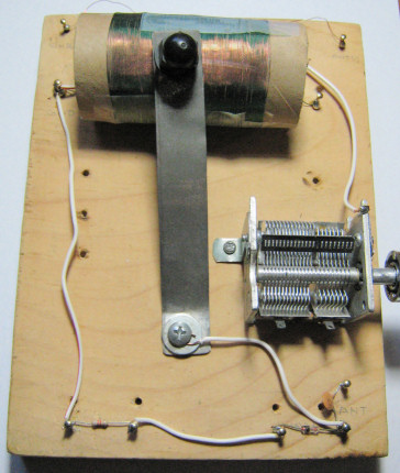
Early Crystal Set - Good for Experimentation
The set had a home wound variable inductor, a 1N34A diode, and an 82k
 resistor in a circuit comprising a simple crystal radio. We piped the output through a Crystal Radio Audio Amplifier circuit for convenience.
The URL giving the amplifier's construction is here:
resistor in a circuit comprising a simple crystal radio. We piped the output through a Crystal Radio Audio Amplifier circuit for convenience.
The URL giving the amplifier's construction is here:
TechLib Crystal Radio Audio Amplifier
Additional testing later included the use of the set's 123 pF ceramic capacitor, a 3.0
 White LED,
an 8
speaker and a small audio frequency transformer pulled from a Radio Shack 100 in 1 kit.
White LED,
an 8
speaker and a small audio frequency transformer pulled from a Radio Shack 100 in 1 kit.
Measurement tools used were a BK Precision 875B LCR meter for capacitance and inductance and a BK Precision "Tool Kit" 2707A Multimeter for current and voltage. The small Crystal Radio Audio Amplifier circuit was also employed to be able to hear the output and provide another way to determine the best location on the variable inductor where the strongest clearest signal would be received.
The base circuit was configured as follows:
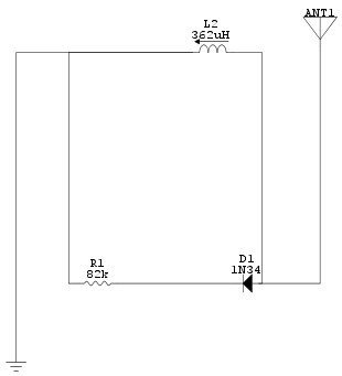
(Graphic produced using CircuitMaker - Student Version 6.2)
The anode of the diode and the antenna were both connected to the variable side of the inductor. The side of the inductor opposite ground was left open. The inductor was 127 closely wound turns of AWG 30 solid copper enameled magnet wire on a 4 cm diameter cardboard form, 6 cm in length.
Its inductance was measured with the LCR meter across its terminals before the antenna or ground wires were connected to the circuit. The inductance of the full coil was 362 pF. The inductance was then tested between the ground side of the inductor and the sliding contact. The usable range available was 4 pF to 341 pF.
Output was measured across the 82k
resistor.
The test was to be performed by attaching the ground and antenna wires to the circuit and then by moving the contact along the variable inductor until the strongest level for the selected station could be heard. At that point, the antenna and ground would be removed and the isolated variable inductor would be tested from the contact to the ground side with the LCR meter to determine the inductance. Using this known inductance and the known frequency of the radio station heard, the capacitance that had made the circuit resonant at the station's frequency could be calculated.
At first, the purely audio method of determining the best point on the inductor was employed. However, in the particular area that this test was performed, (Katy, TX) there is one overpowering (at least for a rather non-selective crystal radio) local (15 miles - 1000 watt) station, KRTX on 980 kHz during the day that actually could be measured somewhat more accurately with a different method. The Multimeter was set to record the voltage across the resistor. As the contact was moved across the variable inductor, the voltage was monitored to find the point at which it was highest. Then, once more, the amplifier was attached to confirm that we had the station and volume we expected. After that, the antenna and ground were removed, along with the amplifier such that the inductance of the variable inductor could be measured.
We used "Professor Coyle's" web calculator:
Professor Coyle - Cylinder Coil Version
to calculate the expected inductance that would be needed to resonate with a 245 pF antenna. It calculated that about 108
 H would be the value.
Test Results
When the circuit was completed, we made five separate measurements of the inductance for the KRTX 980 kHz station. They were 35H,
39 H,
39 H,
35 H,
and 35 H,.
The mode was 35 H,
and the average was 36.6 H.
| Capacitances (Calculated) | |||
|---|---|---|---|
| Measured Inductance | Description | Implied Capacitance | |
| 35 H |
Low and Mode | 754 pF | |
| 36.6 H |
Mean | 720 pF | |
| 39 H |
High | 677 pF | |
This test was then supplemented by attempting to pick out another strong station practically hidden by the local station. Station KRTH 740 kHz (50 000 Watt - 54 miles) could be heard and was the next choice. It was quite difficult, however, to find the exact point it was strongest as the station KRTX 980 kHz almost totally overpowered it. Three observations were made, given the circumstances. They were 64
H,
78 H,
and 73 H.
| Capacitances (Calculated) | |||
|---|---|---|---|
| Measured Inductance | Description | Implied Capacitance | |
| 64 H |
Low | 722 pF | |
| 71.7 H |
Mean | 645 pF | |
| 78 H |
High | 593 pF | |
These results strongly point to an antenna capacitance closer to 700 pF than to 245 pF. But we didn't stop there.
The next test was to insert a small capacitance in series with the antenna to attempt to reduce its capacitance. The existing radio had such a capacitance available; it was 123 pF and was attached to the anode/antenna side of the diode. It was not between the diode and the variable inductor.
The modified circuit was configured as follows:
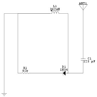
(Graphic produced using CircuitMaker - Student Version 6.2)
If the capacitance of the antenna were 700 pF the combined capacitance would be near 105 pF. If the capacitance of the antenna were 245 pF, the combined capacitance would be near 82 pF.
As expected, this changed the range of frequencies available to test. KRTX 980 kHz was still quite strong and the obvious first choice. We made three observations. They were 224
H,
224 H,
and 260 H.
| Capacitances (Calculated) | |||
|---|---|---|---|
| Measured Inductance | Description | Implied Capacitance | |
| 224 H |
Low and Mode | 118 pF | |
| 236 H |
Mean | 112 pF | |
| 260 H |
High | 101 pF | |
One more station, a higher frequency one, KBRZ 1460 kHz (5 000 Watt - 14 miles) could also be heard. Two observations were recorded for this one; 73.2
H and 74.0 H.
| Capacitances (Calculated) | |||
|---|---|---|---|
| Measured Inductance | Description | Implied Capacitance | |
| 73.2 H |
Low | 162 pF | |
| 74 H |
High | 161 pF | |
Remarks
The second phase of this test with the 123 pF capacitor inserted in the antenna line markedly increased the output of this receiver. Indeed, we measured over 2.5
across the 82k
resistor while tuned to
KRTX 980 kHz. It was the fact that the audio amplifier we had been using was so overloaded that we switched
to the voltage measurements to locate the ideal point on the variable inductor. And, since 2.5
is close
to the required voltage level of a 3.0
LED, we tested what would happen if we connected a white 3.0
LED across the resistor. It lit up at a moderately-low level and flickered according to the modulation
of the signal. See the illustration below:
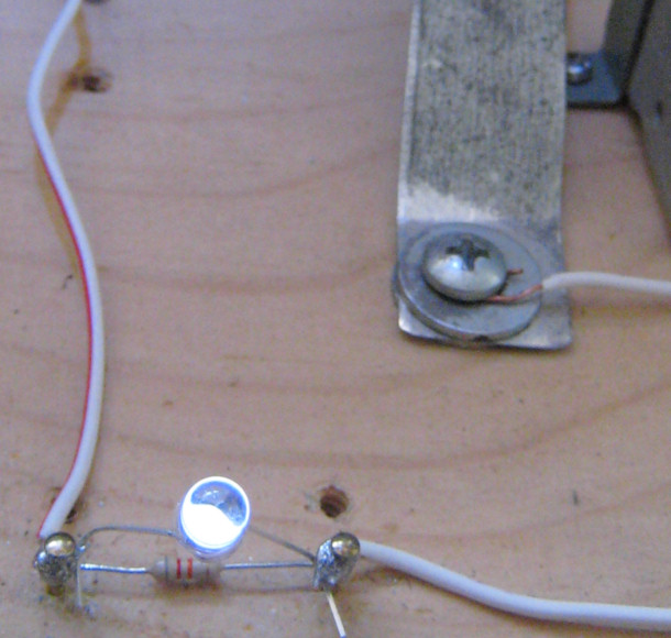
(LED lit with nothing but RF Power from the air!)
Further, we were able to drive a small 2" 8
speaker directly from the radio when we connected it through an audio transformer. (Although it was a poor
impedance match, it was sufficient to work well enough to hear in a quiet room. This was quite impressive for so crude a setup.)