Simpson Microammeter Internal Resistance
How Much Does This Thing Load a Circuit?
The meter being tested here is not anything special. It is an old Simpson 50
 DC ammeter.
I use it to monitor the signal strength of stations
I listen to on my crystal radio. But I became interested in trying to determine, as accurately as possible, the internal resistance of the device.
I learned earlier this year (2009) when I was testing a "joule thief" circuit, that a supposedly low resistance ammeter would markedly affect the circuit I was working with, to the point that I had to come up with a better measurement tool. (That tool turns out to be, put a 1
 resistor in series in the circuit and test the voltage
drop across it. More on that in another page.) I wondered just how much resistance was being presented to a circuit by an ammeter.
Although I did my "joule thief" testing with a digital ammeter, and I did try to come up with a rough idea of the internal resistance for it, I wasn't convinced that I was really calculating out the correct value. So I put those numbers aside and pulled out the analog Simpson meter to make a solid attempt at finding its internal resistance.
The Methodology
The circuit for testing this is simple. A resistor is put in series with a dry cell and the ammeter. The value of the resistor is chosen such that the voltage source will drive the meter to exactly full scale deflection, and no more. I had handy a rechargeable Ni-Cad cell with a voltage of 1.296 . I needed to drop the current to
50
 .
I calculated I should need around 26k
 .
.
I did not want to break the meter by putting in too little resistance to start. I put into the circuit my Cornell-Dubilier RDA-RDB-RDC Resistance Box and set it to 30k
 . This, as expected, was too
much resistance. As I adjusted the dials, I ended up with 23.1k
  as the indicated resistance. I pulled the resistance box out and put in several resistors that came close to the 23.1k
 value. When I connected the power to the circuit again,
I could see that this had worked. The meter's needle was on "50" as closely as I could read it.
The next step should have been simple. Put a shunt resistance in parallel with the meter to drop the current through it to exactly one half scale. I did this, once again using the resistance box to select the correct resistance. It was 1780
 .
.
Two things about this surprised me. First was that the resistance was so high. (Although it was in the ballpark with that I had calculated for the digital ammeter.) And second was that when I tried to tie all the measured numbers together, I was not exactly on target. Oh, yes, they were pretty close. And I knew that this number must be representative of what the resistance actually was. But I wanted a more convincing set of calculations. I also pulled out my Shallcross 638-R Kelvin Wheatstone Bridge to make certain of the resistances. This device can measure resistances at an accuracy level of 0.3% between 1
 and 1 M
 .
After using it here, I am a believer.
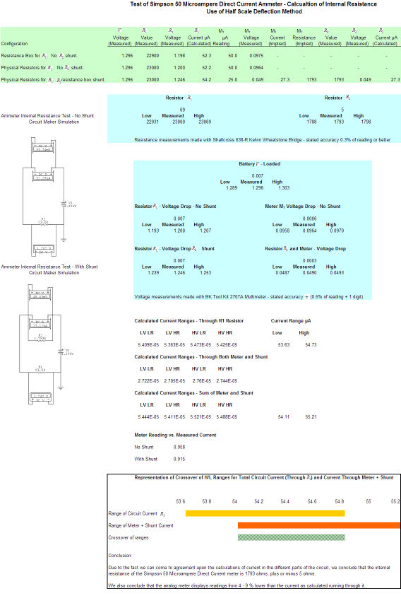
The graphic below may be clicked upon to enlarge it. This is the results of the experimentation as captured in an Excel workbook. I am not going to repeat the stuff I have shown below as the workbook should be self-explanatory, with a little study.
Excel Workbook Calculations and Results
Conclusion
The ammeter has 1793 internal resistance. The numbers
in the workbook confirmed that to my satisfaction. Interestingly, the meter seems to read around 4-9% low when the circuit current is measured
externally, as was done here.
