36 LED - Low Wattage, High Output Spot Lamp
The Idea
LEDs are becoming quite inexpensive (as of July 2008) and as such would seem to offer an attractive alternative to expensive incandescent lighting or possibly even CFLs. I was able to get 100 LEDs (water-clear white 10 000 mcd 3.4 0.020
0.020  ) for $15, delivered,
from eBay. I decided to build a little desk lamp to spot light my projects and studies.
) for $15, delivered,
from eBay. I decided to build a little desk lamp to spot light my projects and studies.
Engineering
Early on, I determined that although you can easily design this project to run on a number of different voltages from 4 - 12+,
if you power it from small batteries, you are going to suck them dry in a matter of a few hours. Especially if you try to use a 9
battery! Even though one
LED takes only 0.020 , when you need 36 times that
0.020 figure, you get a substantial current drain.
My initial tests were with 9 LEDs. I was using a 9
battery.
Since the LEDs are 3+ ,
I decided to try to run 3 paralleled strings of 3 LEDs in series. Each arm would then take 3
and there would be no smoke. The LEDs glowed rather wanly
and I was less than impressed. The 9
battery was delivering only about 7.5
and I was getting about 2.5 across each path.
So, I added another couple of AA batteries in series. Now I had just over 10
... and 9 very bright LEDs!
I decided to build this to use a spare wall-wart (you know, one of those little power transformers for charging a phone, or an old cassette recorder's AC to DC converter? I must have two dozen I've collected over the years.) I selected an Ericsson 6
700 m DC power
supply. It's stated draw from the mains was 10  . When I tested it unloaded, it supplied over 9.6 .
But as I suspected, when I began to load
it up, the voltage fell. I wanted about 6.8 at about 350 m.
Happily, that is just about what I was able to get with this little unit.
. When I tested it unloaded, it supplied over 9.6 .
But as I suspected, when I began to load
it up, the voltage fell. I wanted about 6.8 at about 350 m.
Happily, that is just about what I was able to get with this little unit.
Why 6.8
? Well, most of the AC/DC converters I had were either 6
or less. And the current capacities were for the most part just a
couple of hundred milliamps or so. I needed at least 3.2
for any individual LED. So for various combinations of parallel and series LEDs I calculated I'd need:
| 36 LED Configurations | |||
|---|---|---|---|
| LEDs/Row | Rows | Source V | mA per Row |
| 36 | 1 | 3.2 | 36 * 0.020 = 720 m |
| 18 | 2 | 6.4 | 18 * 0.020 = 360 m |
| 12 | 3 | 9.6 | 12 * 0.020 = 240 m |
| 9 | 4 | 12.8 | 9 * 0.020 = 180 m |
| 6 | 6 | 19.2 | 6 * 0.020 = 120 m |
I wanted to leave a little room above the chosen voltage level so that I wouldn't accidentally overload the lights. They actually are rated 3.2 to 3.8
. As I said,
loading up the chosen AC/DC converter pulled the voltage down from 9.6
very quickly. I could see that three rows could not be made using this component. So a
set of two rows of 18 LEDs each, ideally with 3.4
each should be about what I'd want.
One more point to be made here, and with it perhaps a better understanding why I designed this the way I did. LEDs are current devices. By that I mean they tolerate a certain level of current and no more. The ones I have are rated 0.020 - 0.025 m
maximum forward current. If we apply 3.4 , then we should get a current
that is acceptable. The problem comes in when we cannot get the exact voltage we need. What if all we had available was a steady regulated 5
source?
This is where added resistance in series with the LEDs comes in. If we were to drop the unneeded 1.6
from the 5 in the previous example, across a series resistor, then
we could still end up with 3.4 across the LED. This is perfectly acceptable to do.
However, remember that one of the original thoughts behind this mini-project was to run the LEDs from batteries. If you add resistance, you burn up watts in
the added resistance which give out only infrared light at best. Not only does that not add to the light we can use to see, but it more rapidly depletes
the already limited supply of current the battery can supply.
That said, as you will see, I did end up putting some resistors in the project. The reason for this will be explained as we go on.
Prototype
I built my prototype on a breadboard. It worked quite admirably so I decided to proceed with building a more permanently mounted project. I have made a number of projects in my time, but until now I have never used a PC Board as the base. I figured I'd try that and to make the project as neatly as was possible.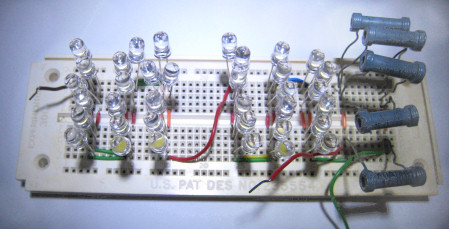
Proof of Concept - Prototype
Design
Now that we know the parallel/series structure we can create a schematic to represent it. There are two resistors in my schematic, both fairly hefty. One handles 4 and the other, 10
.
Why did I choose two rather "mismatched" resistors? If you have to ask, you haven't done much hobby-building. These were pulls from old radios and televisions that I had in my various parts boxes. Not only that, with gasoline at $4/gallon, a 10 mile round trip to Radio Shack costs a fair amount. Honestly, I just hate to buy something when I already have perfectly usable parts. I hesitate to re-use capacitors, but resistors either work and are the right value, or they are in the trash.
But why are they here at all? After I designed this to run on the wall-wart, I thought back to my initial battery design idea. I figured that perhaps I could build this for either AC use or DC use by simply switching in some resistance. I keep a deep cycle EverStart MAXX 29 Marine lead-acid battery in my work area at all times anyway. I can use it with an inverter to turn the lights on in case of a power failure. I decided that I could also use it as a DC source for this LED project.
The current capacity of a lead-acid battery is huge compared to any alkaline cell. I would have current to spare that could be run through a resistor while still leaving days and days of potential use.
How did I figure out what I needed as far as a resistance value? I started with the fact that I was going to want, say, 6.6
only for the LEDs. That left about 12.6 - 6.6 = 6.0
that needed to be dropped across a resistance. How much
current was the series circuit expected to draw? By looking at the table above, we can estimate we will have around 350
m.
Thanks to Mr. Ohm, we can now calculate the required resistance. It is around 17
 .
When I parallelled the 39 and 41 resistors, I measured
right at 21.6 . That was close enough. To calculate the wattage requirement, we
divide the square of the voltage by the resistance. (6.0 )2 / 39
= .92 . and (6.0 )2 / 41
= .88 . Two 1
resistors would suffice. The ones I had were larger wattage handlers so they should stay cooler, even better!
.
When I parallelled the 39 and 41 resistors, I measured
right at 21.6 . That was close enough. To calculate the wattage requirement, we
divide the square of the voltage by the resistance. (6.0 )2 / 39
= .92 . and (6.0 )2 / 41
= .88 . Two 1
resistors would suffice. The ones I had were larger wattage handlers so they should stay cooler, even better!
Schematic
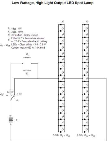
Final Schematic of 36 LED Light
Thanks to Gary Johanson for creating TubePad, a superb freeware collection of bmp schematic symbols. I used several to make the above schematic. Here is a link to Gary's web site:
WD4NKA
Soldering
This mini-project was a practice run for my soldering skills. I have soldered stuff together for years, and had very few clean connections. I had a lot of cold solder joints. I also had a lot of ugly, poorly connected joints, some that solder wouldn't even stick to.Oh sure, I read all the hints about soldering correctly. But they didn't apply to me. I knew what I was doing, it was just that I had a poor soldering iron. (Well, that was what I thought...)
So I bought my first PC board at Radio Shack and prepared to solder in 36 LEDs. You can only imagine the mess. But, given a lemon, I decided to make lemonade. I used that board with five burnt out LEDs soldered to it to practice my soldering. (Did I forget to mention that I had stupidly connected 5 paralleled LEDs to 12.6
? I did?
Well, let me tell you they glowed every color but white, and not even those colors for very long. They all of a sudden smelled real bad too...)
Anyway, there were lots of unused spaces on the board that I started practicing on. I learned that you DO HAVE TO HAVE a scrupulously clean iron, nicely tinned. The parts and board MUST be CLEAN (I used 00 grade steel wool and 220 grit sandpaper. The steel wool was used on the board and the sandpaper on the iron.) And you MUST heat the parts such that the solder will cling to them, not the iron. You need a thin solder, not acid-core, and use it sparingly. The tiny copper circles on the back of a PC Board won't take much before they are connected to 6 of their neighbors! The iron really needs cleaning after every one or two solder joints. After I tried it this way, I found it possible to succeed. Most of my joints were better than average. And the end result was a working project.
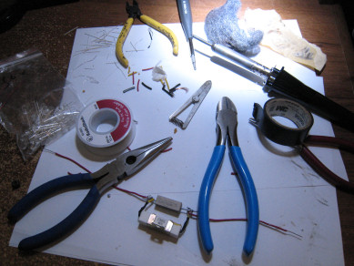
Tools Lit Up by the Finished Light
And this is the finished product in live action!
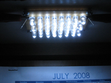
36 LEDs Brightly Shining!
For a more head on view, so that the layout can be seen:
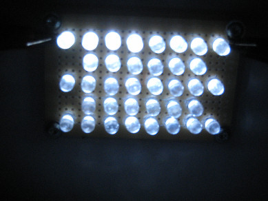
36 LEDs in 5 Rows
Specs
So what are the final measured specs on this device?| 36 LED Project Measured Specs | ||
|---|---|---|
| Parameter | Value | Description |
| Total Voltage - AC Source | 6.67 |
Ericsson 120 Volt 10 Watt AC to DC Converter |
| Total Current - AC Source | 430 m |
Current delivered by converter to circuit |
| LED Power Use - AC Source | 2.87 |
Power used by LEDs (Calculated - P = I * E) |
| Converter Power Use - Drawn from Mains | 6 loaded, 3 unloaded |
(Calculated P = .05 * 120 ) |
| Converter Efficiency | 48% | (Calculated: Pout / Pin ) |
| Total Voltage - DC Source | 12.51 |
Lead-acid battery terminal voltage, loaded |
| LED Voltage | 6.44 |
Voltage across the 36 LEDs - Battery |
| Resistance Voltage | 6.03 |
Voltage across the Resistor Pair - Battery |
| Total Current - DC Source | 279 m |
Current delivered by DC source to circuit |
| Total Power - DC Source | 3.49 |
Power used by LEDs and Resistors |
| LED Power - DC Source | 1.8 |
Power used by LEDs P = .279 * 6.44 |
| Resistor Power - DC Source | 1.68 |
Power used by Resistors P = (6.03 )2 / 21.6 |
Observations and Conclusions
The current draw when the LEDs are connected to the lead-acid battery is considerably less than when they are connected to the converter. There is probably a small reduction in light, but it is not bothersome if there is. The reason is that the resistance I put in the circuit is a bit high. It measures as 21.6 and the design specs said we should have about
17 . The current through each individual LED under these conditions is
about 15.5 m. When run from the mains using the converter, the current through
each LED is closer to 23.9 m.
Now, a bit of economics. Let's work with the condition being that the LEDs are using the converter. This takes 6
total power.
At that rate it would take 167 hours to use a kWh of energy. And, even at the exorbitant rate of 16 cents / kWh, we are looking at 1/10 cent / hr to
generate this light.
The battery holds something like 1 1/2 kWh of energy. If we could draw half of that quantity before we had to charge the battery we could run our lights for something over 100 hours! Indeed, this is a worthwhile project, if for no other reason than for the flexibility it offers as a provider of light under adverse conditions when your choice of power sources may be quite limited.
These particular LEDs have a view angle of plus or minus 7.5°. That is very narrow. They are a tightly focused light provider. If you want something for more general lighting rather than spot lighting, a wide angle like perhaps 30 or 40 ° might be better. And instead of water clear, a diffused case might help too.
And finally, these LEDs, although white, do have a rather strong blue component. That is simply the way they are designed. If you want "white" LED lighting, that is a tradeoff you have to be prepared to make.