Direct Current Circuits
Problem 1-17, Thévenin's Theorem
What is Thévenin's Theorem? Thévenin's Theorem states that any network of constant resistances and voltages
may be represented by a single voltage source with a single resistance in series, as seen from a pair of
open terminals. The voltage across those two terminals is what would be there if the two terminals were shorted.
The resistance is the value that would be measured at the two terminals if all voltage sources in the network were shorted.
The theorem derives in part from the Principle of Superposition. This principle states that if a constant-resistance network has several voltage sources, that each network branch will have several components of current, each attributable to one of the voltages. When these currents are algebraically added, they will sum to the total current in that branch.
The given problem incorporates many Direct Current circuit concepts to solve. We need knowledge of Ohm's Law, Kirchoff's Laws, the use of mesh equations, network simplification, "Y-Delta" transformation, the Principle of Superposition, and last but not least, Thévenin's Theorem itself.
The problem itself looks relatively simple on its face. But it does require a fair amount of work to solve. We start with a look at the schematic and the problem requirements:
.gif)
We are requested to find the current " "
that runs through R5, a 4
  load.
We are to use Thévenin's Theorem to do so. (Actually there is a bit less intensive way, but the object of the
problem is to incorporate the use of all the principles and laws mentioned above, particularly Thévenin's Theorem.)
The component of interest is R5 as that is where the current will be measured. Actually, it is both the resistor R5 and the 24 source V3
in the branch with it. So, the first step we will make is to remove them from the circuit. This will leave the remaining
voltages and resistances to be those that will make up the network where we will apply Thévenin's Theorem.
The reconfigured network looks like this:
.gif)
What we need to do is to get the voltage across the open terminals, and
and  .
That voltage
  , we can calculate with
Ohm's Law and Kirchoff's Laws
through the use of mesh equations.
There are two loops we can work with to calculate the values of and
and  .
These are "abefa" and "bcdeb". We have drawn in some arbitrary directions
for the various currents. The loops we will walk around clockwise to make two voltage equations.


These equations, when solved simultaneously will give:
 and
and

Since is negative,
it means we assumed the direction counter to the actual current direction in loop bcdeb in the model.
Knowing the currents in each branch means we can calculate the voltages across the resistances R3 and R4.


Since the currents and
and  split at point
 and go opposite directions, these two voltages counter one another. The net open terminal voltage is 526.2
 with the positive side at point
 .
.
With the open terminal voltage known, we next calculate the resistance of the network, ,
by reducing the voltage sources in the network to zero. This in effect removes them and replaces each
with a short circuit (wire). To see what this would look like we illustrate the case with the next schematic:
.gif)
What do we do with this to get a net resistance between points and
and
 ? We need to redraw the circuit such that it is in a
recognizable, manipulatable form. A first cut at this redrawing yields this configuration:
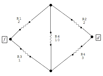
This is helpful, but is not solvable without one more manipulation. We have a delta network of resistors here, actually two deltas, but we need consider only one to achieve a solution. Resistors R1, R3 and R6 are the delta group with which we will work. Here is where we employ some formulas to convert this delta configuration into an equivalent "Y" configuration, which will lend itself to simplification.
The equivalent "Y" network configuration looks like this:
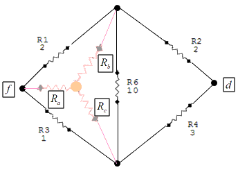
The formulas for calculating ,
,
 ,
and
,
and  are as follows:


Now we can represent the network of these resistors like this:
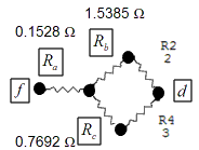
Now what we have offers a solution. is in series with two sets of two resistors, each in parallel with each other.
The equation to solve for the total resistance of the network is:

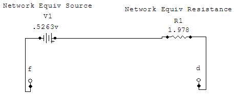
This means that our Thévenin equivalent network is a voltage source of 526.3 in series with a resistance of 1.978
  . The schematic for this
network looks like this:
Finally, we are at the point where we can add back our missing 24 source and our 4
  resistor
that we took out of the original network. To those two components, the entire network of several resistors and
sources that we have been working on appears as a black box that provides 0.5263
  and has 1.978
 of resistance.
Adding those two removed components back, the circuit looks like this:
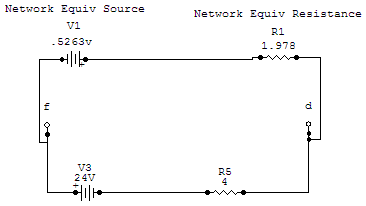
Putting together one final equation around the greatly simplified circuit we calculate .
.

And

The theorem derives in part from the Principle of Superposition. This principle states that if a constant-resistance network has several voltage sources, that each network branch will have several components of current, each attributable to one of the voltages. When these currents are algebraically added, they will sum to the total current in that branch.
The given problem incorporates many Direct Current circuit concepts to solve. We need knowledge of Ohm's Law, Kirchoff's Laws, the use of mesh equations, network simplification, "Y-Delta" transformation, the Principle of Superposition, and last but not least, Thévenin's Theorem itself.
The problem itself looks relatively simple on its face. But it does require a fair amount of work to solve. We start with a look at the schematic and the problem requirements:
.gif)
We are requested to find the current "
 "
that runs through R5, a 4
  load.
We are to use Thévenin's Theorem to do so. (Actually there is a bit less intensive way, but the object of the
problem is to incorporate the use of all the principles and laws mentioned above, particularly Thévenin's Theorem.)
The component of interest is R5 as that is where the current will be measured. Actually, it is both the resistor R5 and the 24
 source V3
in the branch with it. So, the first step we will make is to remove them from the circuit. This will leave the remaining
voltages and resistances to be those that will make up the network where we will apply Thévenin's Theorem.
The reconfigured network looks like this:
.gif)
What we need to do is to get the voltage across the open terminals,
 and
and  .
That voltage
  , we can calculate with
Ohm's Law and Kirchoff's Laws
through the use of mesh equations.
There are two loops we can work with to calculate the values of
 and
and  .
These are "abefa" and "bcdeb". We have drawn in some arbitrary directions
for the various currents. The loops we will walk around clockwise to make two voltage equations.


These equations, when solved simultaneously will give:
 and
and

Since
 is negative,
it means we assumed the direction counter to the actual current direction in loop bcdeb in the model.
Knowing the currents in each branch means we can calculate the voltages across the resistances R3 and R4.


Since the currents
 and
and  split at point
 and go opposite directions, these two voltages counter one another. The net open terminal voltage is 526.2
 with the positive side at point
 .
.
With the open terminal voltage known, we next calculate the resistance of the network,
 ,
by reducing the voltage sources in the network to zero. This in effect removes them and replaces each
with a short circuit (wire). To see what this would look like we illustrate the case with the next schematic:
.gif)
What do we do with this to get a net resistance between points
 and
and
 ? We need to redraw the circuit such that it is in a
recognizable, manipulatable form. A first cut at this redrawing yields this configuration:

This is helpful, but is not solvable without one more manipulation. We have a delta network of resistors here, actually two deltas, but we need consider only one to achieve a solution. Resistors R1, R3 and R6 are the delta group with which we will work. Here is where we employ some formulas to convert this delta configuration into an equivalent "Y" configuration, which will lend itself to simplification.
The equivalent "Y" network configuration looks like this:

The formulas for calculating
 ,
,
 ,
and
,
and  are as follows:


Now we can represent the network of these resistors like this:

Now what we have offers a solution.
 is in series with two sets of two resistors, each in parallel with each other.
The equation to solve for the total resistance of the network is:

This means that our Thévenin equivalent network is a voltage source of 526.3
 in series with a resistance of 1.978
  . The schematic for this
network looks like this:

Finally, we are at the point where we can add back our missing 24
 source and our 4
  resistor
that we took out of the original network. To those two components, the entire network of several resistors and
sources that we have been working on appears as a black box that provides 0.5263
  and has 1.978
 of resistance.
Adding those two removed components back, the circuit looks like this:

Putting together one final equation around the greatly simplified circuit we calculate
 .
.

And
