Crystal Radio Number 2
This radio had a little more planning than the first one I made, although there were still quite a few learnings for me in the building of this little set.I decided to build this radio when I found a cardboard tube about 2 cm in diameter that originally held some rolled up Christmas cotton “snow” material. The tube looked interesting as a candidate for a radio coil I thought. The first set I made employed an empty cardboard toilet tissue roll. It was about 5.5 cm in diameter. So this smaller cardboard tube would make the set look different.
I used the calculator at crystalradio.net to size the coil as far as turns, wire gauge, and length. I wanted something around 240uH.
I used the parameters of .787 inches (2 cm) for the diameter, 30 gauge wire, as closely wound as I could make it, (this turned out to be 7 cm or 2.5”) with 220 turns. The calculator told me that would yield 241.4 uH.
After I got the coil wound with 220 turns (give or take a few) I measured the inductance with my BK Precision 875B LCR meter. It told me that the coil was 284 uH. That is a little more than I expected, but it seemed close enough to me that it should work. I taped the ends of the wire into place.
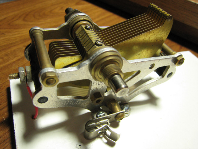
I pulled out of my capacitor box a variable capacitor I have wanted to try. It is a vintage Pilot Centraline (made in the USA) with a range of 16 pf to 342 pf. It is a single gang unit, but with very long rotors and stators made from brass. It does not look like a “standard” tuner and is really quite “industrial age” in appearance.
Theoretically, with a 284 uH coil, this pair should resonate across the range of 512 kHz to 2 365 kHz. That would fully cover the AM Broadcast band and then some.
I used a 1N34 germanium diode for the detector. And I used 4 Fahnestock clips, 2 for the earphone connections and one each for the antenna and the ground. I got the diode and the clips at Mouser.com.
Aside from some hookup wire, a few screws, and some solder, that is where I started.
The schematic for the completed set looks like this:
(Don’t worry about C0 or C2 right now; I purposefully did not mention them yet. They will be discussed.)
When I got the components wired up together, I was a bit disappointed as all I could really hear was one local, very strong Tejano station. (At least it is strong at night.)
Then I started thinking back to the last set I made, before I put a second inductor on it that connected directly to the antenna and ground. I had put a capacitor in series with the antenna before it came into the set. Why? Because some book said that it was a good idea. And it had seemed to help. (But I figured out the real reason which I will explain as we go on.)
So I put another variable capacitor, a 365 pF model, in series with the antenna and tuned it to the spot where the sound was the strongest. I played with the radio a bit more and was finally able to pick out 3 more channels.
I measured the capacitance and found it was around 40 pF. I got three 120 pF capacitors and wired them in series, then replaced the 365 pF variable capacitor with them. Their measured combined capacitance was 43 pF. (Look on the schematic and you will see this as C2.) This worked every bit as well as the variable capacitor.
The frequencies of these four stations were; 610 kHz, 700 kHz, 740 kHz, and 980 kHz. While tuned to each of them individually, I isolated the 342 pF variable capacitor and measured the current capacitance. The following table shows the pF measured and the pF expected, based upon resonance at the given frequencies with a 284 uH coil.
Resonant Capacitance |
||
Frequency kHz |
pF Measured |
pF Expected |
| 610 | 203 | 240 |
| 700 | 144 | 182 |
| 740 | 126 | 163 |
| 980 | 55 | 93 |
In each case the measured capacitance should not have been enough for resonance, yet, that is exactly what I had. It sure seemed like that 43 pF of capacitance I had inserted was being added in, but as may be noted, the difference was not exactly 43 pF; it was a little less. So I thought some more.
At one point in the past, I had decided to measure the capacitance between my antenna and my ground. I had read something about this and I wanted to see what mine was like. The value I obtained when I tried it was 220 pF. Interesting…
Now, if you look back at the schematic once again, you can see there is a different colored line between the antenna and the ground with C0 showing as 220 pF connecting the two. (That is representative of the external, but real capacitance.) We can see that the 220 pF of C0 and the 43 pF of C2 (are in effect) in series with one another. Doing the math, we get a combined capacitance of 36 pF. And, that 36 pF is in parallel with the variable capacitor C1. So it needs to be added to whatever is directly measured for C1 to give the total capacitance in the tank circuit with the 284 uH coil. If you look at the little table just above, you can see the difference between the pF Measured and pF Expected is almost exactly 36 pF in each case. Mystery solved!
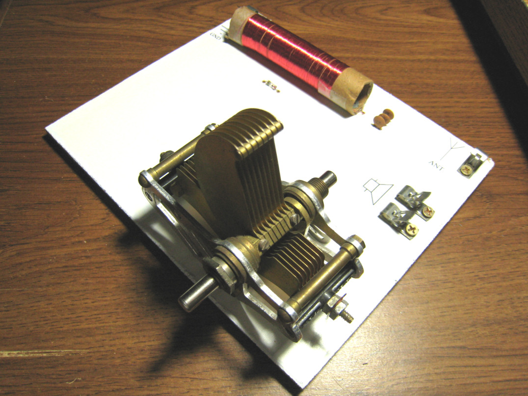
So I assembled the parts on a board. The completed set looks like this:
I started listening for stations during the day. The following table lists what I was able to hear on 12/1/2007.
Stations Heard |
||||
Frequency (kHz) |
Call Letters |
Location |
Distance |
Total Capacitance pF |
| 610 | KILT | Houston | 21.8 mi | 239 |
| 700 | KSEV | Tomball | 30.8 mi | 180 |
| 740 | KTRH | Houston | 50.0 mi | 162 |
| 790 | KBME | Houston | 19.8 mi | 140 |
| 850 | KEYH | Houston | 9.8 mi | 123 |
| 900 | KREH | Pecan Grove | 22.8 mi | 111 |
| 950 | KPRC | Houston | 28.1 mi | 97 |
| 980 | KRTX | Richmond / Rosenberg | 15.0 mi | 91 |
| 1050 | KCHN | Brookshire | 19.1 mi | 80 |
| 1180 | KGOL | Humble | 37.4 mi | 62 |
| 1460 | KBRZ | Missouri City | 14.3 mi | Loudest at 16+36 = 52 pF – Much louder with C2 out of circuit. (Resonance at 42 pF) |
The capacitances agree extraordinarily well with theory. I was able to distinguish many stations, far more than I would have expected. This was a very successful project.
However, it is still a supposedly flawed design, from what I read written by more experienced builders. I should have used multi-stranded wire rather than 30 gauge magnet wire. The turns should not have been as close together. The coil should be much closer dimensionally (length to diameter) to one-to-one than the almost 3 ½ to one that I had.
So, that will probably be addressed in the next radio I build. We'll see how that type of set might compare, using this crystal set as my baseline.
Stations Heard Later and Statistics Recorded:
Additional Stations Heard |
|||||
Frequency (kHz) |
Call Letters |
Location |
Distance |
Date / Time |
|
| 560 | KLVI | Beaumont, TX | approx 90 mi | 12/21/07 6:06PM | |
| 570 | KLIF | Dallas, TX | approx 240 mi | 01/04/08 9:30PM | |
| 710 | KEEL | Shreveport, LA | approx 250 mi | 12/04/07 8:00PM | |
| 820 | WBAP | Ft. Worth, TX | approx 250 mi | 02/06/08 8:20PM | |
| 870 | WWL | New Orleans, LA | approx 350 mi | 01/03/08 8:00PM | |
| 1080 | KRLD | Dallas, TX | approx 240 mi | 01/01/08 8:25PM | |
Using an Amplifier (KSEV 700 Off Air) |
|||||
| 700 | WLW | Cincinatti, OH | approx 1000 mi | 08/23/13 5:10AM | |