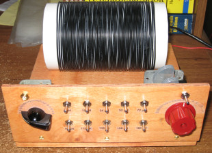
Antenna Enhancer
The Idea
I got the idea from a number of different sources, including many on the 'net that described different crystal radio designs. The main feature this particular one utilizes is a double tuning process. The inductor coil is multiply tapped down its length to give positions to attach an external antenna and simultaneously provide positions to attach an external feed out to a radio. (Normally in a set using a double tuned coil, the second position, the one I use as the external feed, is where the detector crystal or diode is connected to the coil.) There also is a variable capacitance in series with the antenna. It can be used to reduce the built in capacitive effects of a short antenna. This capacitance can be switched into or out of the circuit as desired.
I started this project without a real plan, indeed, not even knowing I was really going to "build" anything. I was trying to wind a tuning coil for a crystal set that was better than the toilet tissue roll variety I had been working with. I experimented with several different diameter cardboard tubes to try and get improvement.
Prototypes
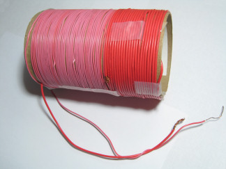
First, I tried to wind a coil on a 5-1/4" Quaker Oats box with about 50 turns of black plastic insulated, single strand 20 AWG wire. I wasn't impressed with the performance.Next I pulled out a nice cardboard tube about 3" in diameter that had been a fancy container for a bottle of wine. I wound this one a bit differently. I tapped the coil about every ten turns or so as I wound it. To make a tap, I just stripped off a bit of the insulation (still using 20 AWG single strand wire) and twisted the end of that wire together with the beginning of the wire for the next coil section. It looked a lot neater than the oat box, but I was still not even close to getting any improvement.
Morton Salt Box - Coil Form
Then just playing around one evening, I took apart a Morton Salt container. It yielded a reasonably substantial 3-1/4" diameter tube, about 5-1/2" long. Since I had just re-strung an antenna outside made up of AWG 18 stranded wire and had taken down the old one, which was 22 AWG single stranded wire, I had some surplus to play with. I wound 22 turns of the AWG 18 onto the tube, then wound 46 more turns on using my old antenna wire. This I measured at a total inductance of 210 uH. Since I hadn't been trying to build a masterpiece, I just twisted the two different wires together in the middle of the coil, making an unintended, but still functional tap. When I measured from the end starting with the old antenna wire, I got 131 uH of inductance. And measuring from the end with the stranded wire, I saw 39 uH.When I put this coil in parallel with a 365 pF variable capacitor, it worked better than any of the other coils that I had worked (relatively) harder to wind! And I could vary the range of tuning even further by tying the antenna to the tap rather than to one end of the coil. I decided to attempt a more permanent example of this prototype.
Starting A Project - But Not Really Knowing It Yet
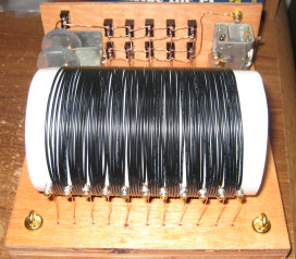
I read that PVC pipe makes a good coil form. I went to Lowe's and purchased a 3' long section of 3-3/8" O.D. PVC pipe for about $6. It was as close in diameter to the 3-1/4" salt container tube that I could find. I also got some #4 brass screws while I was there to use as tap points on the coil. And for the coil itself, I bought a 100' roll of wire (black plastic, insulated, stranded AWG 20) from Radio Shack.I cut off a piece of PVC 6" long, intending to wind a 5-1/2" long or so coil. Starting 1/2" from the end, I drilled 11 one-sixteenth inch holes spaced 1/2" apart in a straight line along the PVC. I put a brass screw into each hole, leaving about 1/4" protruding above the surface of the pipe. I was able to wind six turns between each screw, thereby getting 60 turns total. I soldered each section of wire to the brass tap points where they began and ended.
My intention was to get a bit more inductance out of the new coil than I had in the Morton Salt one. As it turned out, I ended up with a bit less due to the greater diameter of the wire I was using. The measured total inductance was 180 uH. This was a little low, but still OK as I figured I could add a bit of capacitance to my variable capacitor if I needed to so that I could get to the bottom end of the Broadcast band.
When I used this coil with a 365 pF variable capacitor, it made a noticeable improvement in the volume of stations to which I was trying to listen. I inductively linked the coil to the coil on the sets I was listening to and was impressed with the improvement. I also tried the coil in a circuit with a diode detector and found it worked well on its own as a radio, too.
The ability to place the antenna at multiple tap points really made a large difference in what I could get out of my crystal receiver. So I knew that I wanted to build a permanent setup to use this coil. But I had a hard time deciding if I should make it into a radio of its own, or to use it as a tool to increase antenna strength. I finally decided that I would be able to use this on multiple radios if I made it as an antenna booster. So that is the route I took.
Making The Base
Rather than build this one on a ratty piece of scrap wood, I decided to make it nicer by using a higher quality wood board. I didn't have anything usable lying around, so back to Lowe's. I looked at the pine wood; it was too knotty or too yellow. I looked at some of the top grade hard wood boards. Yes, they were very nice, but I am not one of your better carpenters. And I decided not to destroy a fine piece of wood with my incompetence. So, I settled on a piece of birch. It was clear, white, and not too expensive. Yes, it is rather soft, but I cannot think of a better choice to practice on, as it is relatively inexpensive. I got a 2' x 4' x 1/2" piece for about $10.The PVC was 6" long, so I figured an 8" wide base would be good. I decided to make the base square, as that should accommodate all the parts I wanted to put on it. Using my Skil jigsaw, I cut out the 8" x 8" piece. Surprisingly, I managed to get a reasonably straight set of cuts. (I really need a table saw if I plan to continue doing this. It is just too hard to make straight cuts by hand with a jigsaw, or even with a circular saw.) I filed and sanded the edges to get smooth surfaces and to prevent myself from getting a bunch of splinters.
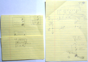
Prototype Sketches
Then I had to figure out how I wanted the parts layout to look. Quickly, I understood that I wanted a front panel as there were going to be some controls on this project and they needed proper mounting.What I really wanted was a rotary switch where I could click-select the desired tap on the coil. Although I have since located a source for such a switch, I had a hard time finding anything I could quickly acquire. So, I decided to go with a bunch of toggle switches. I found some on eBay. While I was browsing around for them, I decided to look for SPDT switches so that I could put either the antenna in or the output to the radio at a given coil tap point. Ten switches, using two at a time to tap the coil at different points seemed like a good way to go.
Good Time To Draw Some Plans...
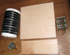
Now I began to draw the proposed designs for the front panel. At last, I settled on one 8" long and 3" high. But when I got the switches, I saw that they were not quite as large as I had envisioned them to be.Antenna Enhancer - The Basic Parts
I couldn't use the 1/2" birch I had and be able to get them to go through it. So...once again, I went back to Lowe's. I found a nice piece of poplar this time, 3/16" thick, and 2' x 2'. The color was quite similar to that of the birch. It cost something like $5. I cut out my 3" x 8" piece with the Skil jigsaw. Again, I struggled to get a straight cut. It ended up being straight enough, but I can see the flaws. At this point, I had my wood pieces cut, my hardware ready, and my electronic parts there. Ready to go...NOT!I kept looking at the wood and knowing that although I should, but did not want to spend the time to do so, I needed to stain and varnish it. (Again, I tell you I am a poor carpenter.)
Antenna Enhancer - The (Very) Dry Fit
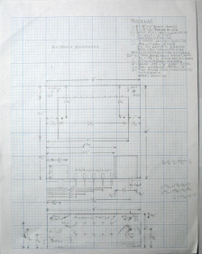
But poor carpenter or not, I hate doing something poorly or the wrong way. I still did not have the mounting holes drilled in the wood. Until that was done, I wasn't ready to stain anything. So, I pulled out my graph paper and commenced to make some scale drawings and locate where the drilling work would take place.Doing this took hours over a number of days. I struggled with different design possibilities. Finally, I made my decisions and was ready to start drilling.
Making The First Holes
Before I could drill, I had to lay out the precise locations on the wood. I spent quite a while transferring my designs from paper to the wood. I'll spare you the details of drilling. Let's just say it went as well as I could have expected it to.The Plans
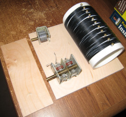
Part of the reason I procrastinated was that it had taken considerable effort to cut the base and the front piece of wood. I dreaded making a mistake and having to start over. But I began to understand that I had no real choice. I knew I had to learn how to do these tasks while on-the-job.As I dry fitted the parts together, it became clear that I needed to have some way of lifting the under-base wiring up from where the base was sitting. Otherwise, I risked potentially shorting out the circuit or worse yet, ripping loose some wires.
After some thought, I decided that some 1/2" x 1/2" strips along the bottom of the base would do the trick.
And I had also figured out an interesting way to put some tiny feet under those strips to add a little
more class to the project. So, one more time...back to Lowe's.
Addition To The Design...Get More Parts
There was nothing at Lowe's along the lines of pre-cut 1/2" x 1/2" birch stock. But I was able to get the hardware for the feet and the stain and spray varnish while I was there.To make the 1/2" x 1/2" strips, I worked with the large remaining piece of the 2' x 4' x 1/2" birch board I had. This time, the cuts I made with the jigsaw were truly not straight. I was able to get close to the lengths I needed, 2 - 8" and 2 - 7" strips. But the cuts, which I was able to locate on the inside of the strips, where they cannot be seen unless you look under the project, were not satisfactory to me. The only reason I used these pieces was that I know that with my limited set of hand tools and overall lack of carpenter's skills, I would not end up with a much better product even were I to try again.
These parts I also had to drill and countersink to accommodate the feet I wanted to put on. I sanded these parts smooth as well.
Stain, Varnish, and...
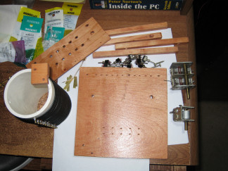
Antenna Enhancer - A Bunch of Parts
At last, I was ready to stain and varnish the birch and poplar pieces. I used some wood surface prep that you put on prior to staining to help the wood absorb the stain evenly. It worked well. Then the maple colored stain went on smoothly. After wiping off the excess stain and allowing the pieces to dry overnight, I was ready to spray varnish them. I moved the parts outside and gave them three coats of varnish over the next several hours.When they were dry, I looked at what I had accomplished. I think for a non-carpenter, the end-result is acceptable. Norm Abram might blanch at the work quality, but I was satisfied that I could live with what I had turned out.
Hmm...This Is Taking a Lot Longer Than I Thought
It was time to start putting the parts together. It didn't take me long to see that a drawing or a completed project in the mind's eye is very different from actually hanging the real parts together on the boards.The first thing I learned was that the little block that I made for the main tuning variable capacitor to sit on had been placed too close to the front panel. The reason for this problem was that I had chosen the front side of the capacitor to be where I would attach a brass strap to hold the part down. However, when I did this, neither a machined down screw nor even a twisted wire held with solder would fit into the little gap I had on the front of the block and still allow the front panel to go on flush with the base. Finally, after much flattening of the solder and screwing the front on tightly, I was able to get the front on "good enough". I guess you can see it, if you look for it. But it will do as I do not wish to drill new holes to move the block back 2 mm or some such trivial distance.
Another thing that I have described above is the lack of the proper tooling. If I had a table saw and a drill press, this project would have gone faster and been easier to get right the first time. So those may soon grace my garage.
I saw that I hadn't drilled every hole that I needed. Fortunately, they were only 1/16th" holes that needed drilling (3 of them) and they went in pretty easily. The holes that I needed to drill in the tiny brass strips to hold the variable capacitors were not real easy though. However, I stumbled on a good trick to use with brass sheet cutting and drilling while making this project. If you clamp the brass between two sheets of wood, you can cut and drill without bending up the brass. A great idea!
Coming Together...
Somehow, I got it together. I decided to wire the parts together with some 22 AWG Brass colored magnet wire. I chose it because of its color and its relative stiffness. I wanted the wiring visible and wanted it to look as attractive as possible.Antenna Enhancer - View from Behind
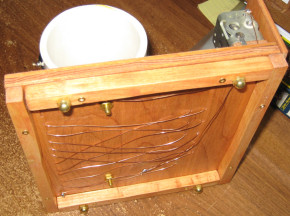
I had drilled 11 holes behind where I wanted the coil to go. The idea was to have the magnet wire come down from each of the 11 connection points there, be threaded underneath to holes near the front, and then get threaded back up to connect to the 10 switches. That seemed to work pretty well.I wasn't sure what I was going to use for my antenna and ground connectors, until I saw the brass threaded eye hooks that I ended up installing. Actually, they were part of a little kit from Hillman of Cincinnati. They were in a " 3" Gate Hook and Eyes Brass" set. The first eye hook was loose. The second eye hook had the brass latch bent through it. I just put that latch in the vice and pried it open to release the eye hook.
Antenna Enhancer - Underneath
Then I used a couple of Hillman "#10 Finish Washers Brass" under the eye hooks. I think it turned out pretty neat looking. These connectors have the antenna and ground attach to them with alligator clamps. The screws come all the way through the base and have wires soldered to them.I attached the coil itself to the base with two "10-24 x 1-1/4" Round Slotted Brass" screws, run through a couple more of the "#10 Finish Washers Brass", and tied down with two "10-24 Hex Nuts Brass". It won't move.
The 1/2" x 1/2" strips are held on to the base with eight "4 x 3/4 Flat Phillips Brass" wood screws. The little legs are "Acorn Nuts Brass Plated". They each are attached to a "10-24 x 3/4 Flat Slotted" screw that is countersunk into the top side of the strips and are hidden from view. Legs make it easier to get my fingers under the thing to move it.
Pretty Much Done
Antenna Enhancer - Front
The front panel is held in place by three "4 x 1/2 Round Slotted Brass" screws. The knobs are not the final ones I will use, but for now they are what I have available. The little brass coax connector at the upper left is the output where an external radio gets its "Antenna Enhanced". The connector doesn't really act as a coax connector. It is just another attractive brass connection point where I attach an alligator clip. (I got it from a wireless PC card that hadn't any more use.)The labels are not the best, but I still don't quite know what might be better. These are transparent address labels that I printed the desired words and symbols on, cut them to size, then stuck them on the front. They serve their purpose so I suppose I'll leave them there.
I calibrated the variable capacitors by first taking them out of the circuit. Then I carefully measured the capacitance with my LCR meter as I ran the rotors from closed to open. I had to move the numbers repeatedly in the document where I set up the graphic to print them. But I eventually got numbers the right size and in the correct positions to look pretty good (if a little small though).
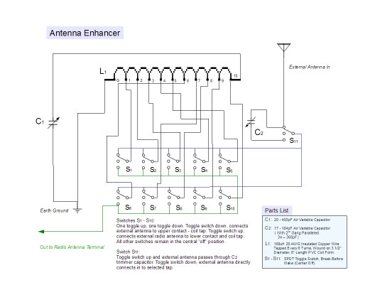
Schematic (Made 11/1/08)
Antenna Enhancer SchematicWhat's Left to Do?
Plenty! I need better knobs, better labels, more identification of parts' functionality, and maybe a bottom board to enclose the wiring completely. Mainly, I need to map out how to use it for the most effective listening, both for DXing and for selectivity.
After All That... Does It Work?
You Betcha! It is an awesome enhancer for my antenna. I knew it would work before I built it though. When I had the PVC tapped coil already made I hooked it to a variable capacitor and all kinds of wires such that I could swap out the antenna and detector connections up and down the coil. I could tell it would really increase the strength and selectivity of my antenna input. I finally got tired of swapping out the connections by hand and figured a more permanent arrangement would be in order.Specs and Use
There is an input connection point for each of an antenna and a ground. The antenna connection is at the right rear and the ground connection is at the left rear. There is one connection point out for an external radio to use as an antenna input source. It is on the top left of the front panel of the set.There are two variable capacitors. The one on the left ranges from 20 pF to 400 pF. It is in parallel with the coil, where it is permanently attached to each end. The second variable capacitor on the right just uses one of the two gangs (generally). The scale ranges from 17 pF to 184pF. It is useful under certain conditions to hook both gangs in parallel to get more capacitance. The two gangs are close to the same value and range, so when they are paralleled, the total range is from 34 pF to 368 pF. The switch (immediately above the scale) when flipped down will switch this capacitor into series with the incoming antenna connection. The same switch when flipped up will bring the antenna in directly, thereby bypassing the capacitor. When in the middle position it connects to nothing, as is the case with all the switches in this project.
There are ten switches across the middle of the front panel. Each represents a uH value from where it taps the coil to ground. The values range from 6uH to 180uH. Switch S1 taps at 6 uH and switch S10 is the full coil at 180 uH. When a switch is flipped up, it connects the output connection to that tap. When a switch is flipped down, it connects the antenna input to that coil tap position.
In general, the higher the uH, the stronger the signal, but less selective the tuning. As the uH is reduced, there is less volume, but much better selectivity. Also, with a lower uH selected, I am better able to get more of the top end of the broadcast band. As I get better and more specific statistics from the use of this tool, I will post them here.
